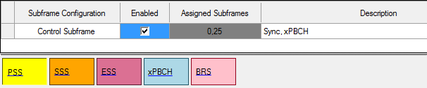
Control Subframe
Control subframe always exists in the subframe list. It can be turned off but cannot be removed. The Assigned Subframe property is read-only and fixed to ‘0, 25’. The common channels in control subframe are PSS, SSS, ESS, xPBCH and BRS. There are colored blocks that are representing these channels. When a channel is turned off, the associated block will turn gray.
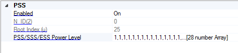
PSS
The primary synchronization signal is used to acquire symbol timing and transmitted in symbol 0-13 in subframes 0 and 25 on antenna ports 300 ~ 313.
Enabled
Select/ deselect the Enable check box to enable/ disable the channel or signal in a radio frame.
This parameter is applicable to all channels.
N_ID(2)
Display N_ID(2) within a cell ID group.
This is read-only and determined by: Cell ID = N_ID(1) *3 + N_ID(2)
Root Index(u)
The Root Index(u) field displays root index (u) for PSS sequence generation. This value is determined by N_ID(2).
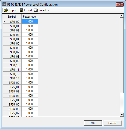
PSS/SSS/ESS Power Level
Opens the Power Level Configuration Editor to configure the power level for each symbol of subframe 0 and subframe 25 of PSS/SSS/ESS. The unit in the table is ratio, not dB, so 1 means no change, and 0 means no power.
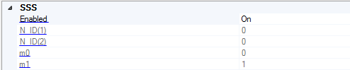
SSS
The secondary synchronization signal is transmitted in symbol 0-13 in subframes 0 and 25 on antenna ports 300 ~ 313.
Enabled
Select/ deselect the Enable check box to enable/ disable the channel or signal in a radio frame.
N_ID(1)
The N_ID(1) field displays N_ID(1) that is the cell ID group number. This value is determined by carrier Cell ID.
N_ID(2)
Display N_ID(2) within a cell ID group.
This is read-only and determined by: Cell ID = N_ID(1) *3 + N_ID(2)
m0
The m0 field displays m0 for SSS sequence generation. m0 is determined by N_ID(1).
m1
The m1 field displays m1 for SSS sequence generation. m0 is determined by N_ID(1).
ESS
The extended synchronization signal is used to identify the OFDM symbol index and transmitted in symbol 0-13 in subframes 0 and 25 on antenna ports 300 ~ 313.
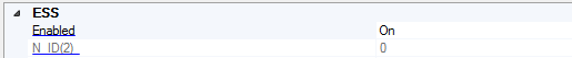
Enabled
Select/ deselect the Enable check box to enable/ disable the channel or signal in a radio frame.
N_ID(2)
Display N_ID(2) within a cell ID group.
This is read-only and determined by: Cell ID = N_ID(1) *3 + N_ID(2)
xPBCH
The physical broadcast channel is transmitted using the same beams used for beam reference signals in each OFDM symbol.
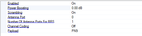
Enabled
Select/ deselect the Enable check box to enable/ disable the channel or signal in a radio frame.
Power Boosting
Range: -40 - 40
Default: 0
Set the additional power boosting for the channel.
DMRS Power Boosting
Range: -40 - 40
Default: 0
Set the DMRS power relative to data part.
Scrambling
Enable or disable the scrambling for the channel.
Antenna Port
Set the antenna port on which the symbols will be generated into the waveform.
xPBCH uses the same antenna port as BRS.
Number of Antenna Port for BRS
Choices: 1 | 2 | 4 | 8
Default: 1
Set the number of BRS antenna ports for CRC scrambling.
Channel Coding
Enable or disable transport layer channel coding. When disabled, raw payload data will be passed to scrambler directly.
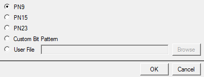
Payload
Choices: PN9 | PN15 | PN23 | Custom Bit Pattern | User File
Default: PN9
Bring up the  Payload Editor to select the data bits used for the channel payload.
BRS
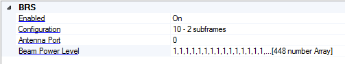
Enabled
Select/ deselect the Enable check box to enable/ disable the channel or signal in a radio frame.
Configuration
Choices: 00 - 1 | 01 - 1 | 10 - 2 | 11 - 4
Default: 10 - 2
Select the BRS configuration that defines BRS transmission period.
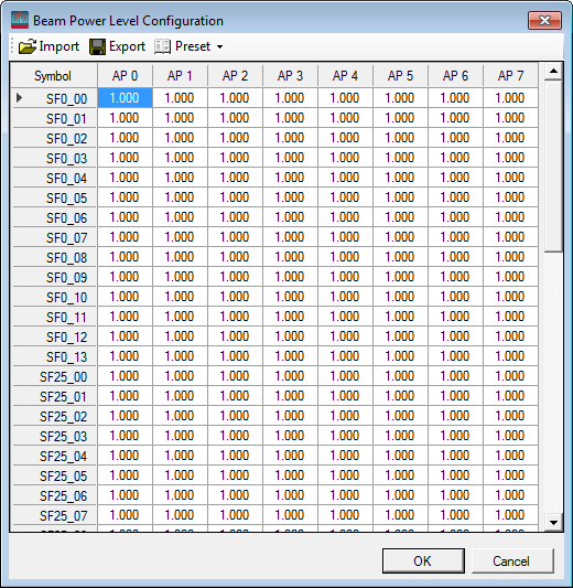
Beam Power Level
Opens the Beam Power Level Configuration Editor to configure the power level for each beam.
The size of the table for Beam Power Level configuration is always be 56 by 8 and does not depend on the BRS configuration. The waveform generation algorithm picks the corresponding power values from the table according to the BRS configuration.
-
For BRS configuration = 00, the BRS transmission period is 1 slot, so only the first seven rows are used, that is, symbol 0 ~ 7 of SF0.
-
For BRS configuration = 01, the BRS transmission period is 1 subframes, so only the first 14 rows are used, that is, symbol 0 ~ 13 of SF0.
-
For BRS configuration = 10, the BRS transmission period is 2 subframes, so only the first 28 rows are used, that is, symbol 0 ~ 13 of SF0 and SF25.
-
For BRS configuration = 11, the BRS transmission period is 4 subframes, so all the values are used, and in this case, the Number of Radio Frame under Waveform Setup node should be 2.
The power level value in the table is a ratio, not dB, so 1 means no power change, 0 means no power. For now, only waveform for one antenna port can be generated, so although the table contains power configuration for all antenna ports, only one antenna port is used for each generation.
Antenna Port
Set the antenna port on which the symbols will be generated into the waveform.
xPBCH uses the same antenna port as BRS.